Implementing a secure high-availability network infrastructure with a dedicated DMZ based on the UserGate NGFW

Follow this tutorial to deploy a secure network infrastructure based on the UserGate next-generation firewall. The infrastructure is made up of segments, each containing single-purpose resources, isolated from other resources. For example, the DMZ segment is reserved for public-facing applications, whereas the mgmt segment contains infrastructure management resources. Each segment will have its own cloud folder and a dedicated VPC cloud network. The segments communicate with each other via a next-generation firewall (NGFW) VM, which provides end-to-end protection and traffic control across the segments.
You can see the solution architecture in the diagram below.
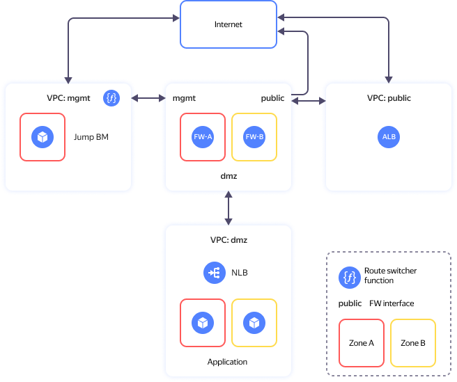
The solution comprises these main segments (folders):
- The public folder contains the internet-facing resources.
- The mgmt folder is for cloud infrastructure management and internal resources. It includes two VMs for infrastructure protection and network segmentation into security zones (
fw-aandfw-b) and a VM with WireGuard VPN configured for secure access to the management segment (jump-vm). - dmz that enables you to publish open-access applications.
For more information, see the project repository.
To deploy a secure high-availability network infrastructure with a dedicated DMZ based on the UserGate next-generation firewall:
- Get your cloud ready.
- Set up your environment.
- Deploy your resources.
- Configure the NGFW.
- Enable the route switcher.
- Test the solution for performance and fault tolerance.
- Requirements for production deployment.
If you no longer need the resources you created, delete them.
Next-Generation Firewall
An NGFW is used for cloud network protection and segmentation with a dedicated DMZ for public-facing applications.
Yandex Cloud Marketplace offers multiple NGFW solutions. This scenario uses UserGate NGFW. Its features include:
- Firewalling.
- Intrusion detection and prevention.
- Traffic management and internet access control.
- Content filtering and application control.
- VPN server.
- Stream-based antivirus.
- Protection against DoS attacks and network flooding.
In this tutorial, we use the UserGate NGFW configuration with basic firewall and NAT rules.
Learn more about what UserGate NGFW can do in the vendor’s documentation.
Get your cloud ready
Sign up for Yandex Cloud and create a billing account:
- Navigate to the management console and log in to Yandex Cloud or create a new account.
- On the Yandex Cloud Billing page, make sure you have a billing account linked and it has the
ACTIVEorTRIAL_ACTIVEstatus. If you do not have a billing account, create one and link a cloud to it.
If you have an active billing account, you can create or select a folder for your infrastructure on the cloud page.
Learn more about clouds and folders here.
Required paid resources
The infrastructure support cost includes:
- Fee for continuously running VMs (see Yandex Compute Cloud pricing).
- Fee for using Application Load Balancer (see Yandex Application Load Balancer pricing).
- Fee for using Network Load Balancer (see Yandex Network Load Balancer pricing).
- Fee for using public IP addresses and outgoing traffic (see Yandex Virtual Private Cloud pricing).
- Fee for using functions (see Yandex Cloud Functions pricing).
- Fee for using UserGate NGFW.
Required quotas
Warning
In this tutorial, you will deploy a resource-intensive infrastructure.
Make sure you have sufficient cloud quotas not used by other projects.
Resources used by this tutorial
| Resource | Quantity |
|---|---|
| Folders | 3 |
| Instance groups | 1 |
| VMs | 5 |
| VM vCPUs | 14 |
| VM RAM | 38 GB |
| Disks | 5 |
| SSD size | 400 GB |
| HDD size | 30 GB |
| Networks | 3 |
| Subnets | 6 |
| Route tables | 2 |
| Security groups | 6 |
| Static public IP addresses | 4 |
| Public IP addresses | 4 |
| Static routes | 5 |
| Buckets | 1 |
| Cloud functions | 1 |
| Cloud function triggers | 1 |
| Total RAM for all running functions | 128 MB |
| Network load balancers (NLB) | 2 |
| NLB target groups | 2 |
| Application load balancers (ALB) | 1 |
| ALB backend groups | 1 |
| ALB target groups | 1 |
Set up your environment
Create a cloud administrator service account
-
In the management console, select the folder where you want to create your service account.
-
Navigate to Identity and Access Management.
-
Click Create service account.
-
Name your service account, e.g.,
sa-terraform.The naming requirements are as follows:
- Length: between 3 and 63 characters.
- It can only contain lowercase Latin letters, numbers, and hyphens.
- It must start with a letter and cannot end with a hyphen.
Make sure the service account name is unique within your cloud.
-
Click Create.
-
Assign the admin role to the service account:
- On the management console home page, select your cloud.
- Navigate to the Access bindings tab.
- Click Configure access.
- In the window that opens, click Service accounts and select the
sa-terraformservice account. - Click Add role and select the
adminrole. - Click Save.
If you do not have the Yandex Cloud CLI yet, install and initialize it.
The folder used by default is the one specified when creating the CLI profile. To change the default folder, use the yc config set folder-id <folder_ID> command. You can also specify a different folder for any command using --folder-name or --folder-id. If you access a resource by its name, the search will be limited to the default folder. If you access a resource by its ID, the search will be global, i.e., through all folders based on access permissions.
-
Create a service account:
yc iam service-account create --name sa-terraformWhere
nameis the service account name. The naming requirements are as follows:- Length: between 3 and 63 characters.
- It can only contain lowercase Latin letters, numbers, and hyphens.
- It must start with a letter and cannot end with a hyphen.
Result:
id: ajehr0to1g8b******** folder_id: b1gv87ssvu49******** created_at: "2024-01-04T09:03:11.665153755Z" name: sa-terraform -
Assign the admin role to the account:
yc resource-manager cloud add-access-binding <cloud_ID> \
  --role admin \
  --subject serviceAccount:<service_account_ID>
Result:
done (1s)
To create a service account, use the create REST API method for the ServiceAccount resource or the ServiceAccountService/Create gRPC API call.
To assign the service account a role for a cloud or folder, use the updateAccessBindings REST API method for the Cloud or Folder resource:
-
Select the role to assign to the service account. You can find the description of the roles in the Yandex Identity and Access Management documentation in the Yandex Cloud role reference.
-
Get the ID of the service accounts folder.
-
Get an IAM token for authentication in the Yandex Cloud API.
-
Get a list of folder service accounts to find out their IDs:
export FOLDER_ID=b1gvmob95yys********
export IAM_TOKEN=CggaATEVAgA...
curl \
  --header "Authorization: Bearer ${IAM_TOKEN}" \
  "https://iam.api.cloud.yandex.net/iam/v1/serviceAccounts?folderId=${FOLDER_ID}"
Result:
{ "serviceAccounts": [ { "id": "ajebqtreob2d********", "folderId": "b1gvmob95yys********", "createdAt": "2018-10-18T13:42:40Z", "name": "my-robot", "description": "my description" } ] } -
Create the request body, e.g., in the
body.jsonfile. Set theactionproperty toADDandroleIdto the appropriate role, such aseditor, and specify theserviceAccounttype and service account ID in thesubjectproperty:body.json:
{ "accessBindingDeltas": [{ "action": "ADD", "accessBinding": { "roleId": "editor", "subject": { "id": "ajebqtreob2d********", "type": "serviceAccount" } } }] } -
Assign a role to a service account. For example, for a folder with the
b1gvmob95yys********ID:export FOLDER_ID=b1gvmob95yys******** export IAM_TOKEN=CggaAT******** curl \ --request POST \ --header "Content-Type: application/json" \ --header "Authorization: Bearer ${IAM_TOKEN}" \ --data '@body.json' \ "https://resource-manager.api.cloud.yandex.net/resource-manager/v1/folders/${FOLDER_ID}:updateAccessBindings"
Install the required tools
-
Install Git using the following command:
sudo apt install git -
Install Terraform:
-
Navigate to the root directory:
cd ~ -
Create the
terraformdirectory and open it:mkdir terraform cd terraform -
Download the
terraform_1.9.5_linux_amd64.zipfile:curl \ --location \ --remote-name \ https://hashicorp-releases.yandexcloud.net/terraform/1.9.5/terraform_1.9.5_linux_amd64.zip -
Install
zipand unpack the ZIP archive:apt install zip unzip terraform_1.9.5_linux_amd64.zip -
Add the path to the directory with the executable to the
PATHvariable:export PATH=$PATH:~/terraform -
Make sure Terraform is installed by running this command:
terraform -help
-
-
Create a configuration file specifying the Terraform provider source:
-
Create the
.terraformrcfile innano:cd ~ nano .terraformrc -
Add the following section to the file:
provider_installation {
  network_mirror {
    url = "https://terraform-mirror.yandexcloud.net/"
    include = ["registry.terraform.io/*/*"]
  }
  direct {
    exclude = ["registry.terraform.io/*/*"]
  }
}
Read more about mirror settings in this Terraform guide.
-
Deploy your resources
-
Clone the GitHub repository and navigate to the
yc-dmz-with-high-available-usergate-ngfwscript directory:git clone https://github.com/yandex-cloud-examples/yc-dmz-with-high-available-usergate-ngfw.git cd yc-dmz-with-high-available-usergate-ngfw -
Set up your CLI profile to use the service account to run operations:
CLIIf you do not have the Yandex Cloud CLI yet, install and initialize it.
The folder used by default is the one specified when creating the CLI profile. To change the default folder, use the
yc config set folder-id <folder_ID>command. You can also specify a different folder for any command using--folder-nameor--folder-id. If you access a resource by its name, the search will be limited to the default folder. If you access a resource by its ID, the search will be global, i.e., through all folders based on access permissions.-
Create an authorized key for your service account and save it to the file:
yc iam key create \
  --service-account-id <service_account_ID> \
  --folder-id <ID_of_folder_with_service_account> \
  --output key.json
Where:
service-account-id: Service account ID.folder-id: ID of the folder where you created the service account.output: Authorized key file name.
Result:
id: aje8nn871qo4******** service_account_id: ajehr0to1g8b******** created_at: "2023-03-04T09:16:43.479156798Z" key_algorithm: RSA_2048 -
Create a CLI profile to run operations under the service account:
yc config profile create sa-terraformResult:
Profile 'sa-terraform' created and activated -
Configure the profile:
yc config set service-account-key key.json
yc config set cloud-id <cloud_ID>
yc config set folder-id <folder_ID>
Where:
-
Add the credentials to the environment variables:
export YC_TOKEN=$(yc iam create-token)
-
-
Get your PC's IP address:
curl 2ip.ruResult:
192.2**.**.** -
Open the
terraform.tfvarsfile innanoand edit the following:-
Cloud ID line:
cloud_id = "<cloud_ID>" -
Line with a list of public IP addresses allowed to access
jump-vm:trusted_ip_for_access_jump-vm = ["<external_IP_address_of_your_PC>/32"]
terraform.tfvarsvariable descriptionParameter
nameChange
requiredDescription Type Example cloud_idYes Your Yandex Cloud ID stringb1g8dn6s3v2e********az_name_list- List of two Yandex Cloud availability zones to host your resources list(string)["ru-central1-a", "ru-central1-b"]security_segment_names- Segment names. The first segment is for management resources, the second, for internet-facing resources, and the third, for DMZ. If you need more segments, add them at the end of the list. When adding a segment, make sure to specify the subnet prefixes in zone1_subnet_prefix_listandzone2_subnet_prefix_list.list(string)["mgmt", "public", "dmz"]zone1_subnet_prefix_list- List of network prefixes in the first availability zone for subnets mapped to the security_segment_nameslist. Specify one prefix for each segment from thesecurity_segment_nameslist.list(string)["192.168.1.0/24", "172.16.1.0/24", "10.160.1.0/24"]zone2_subnet_prefix_list- List of network prefixes in the second availability zone for subnets mapped to the security_segment_nameslist. Specify one prefix for each segment from thesecurity_segment_nameslist.list(string)["192.168.2.0/24", "172.16.2.0/24", "10.160.2.0/24"]public_app_port- TCP port for a DMZ application open for internet connection number80internal_app_port- DMZ application internal TCP port receiving traffic from NGFW. You may specify the same port as public_app_portor a different one.number8080trusted_ip_for_access_jump-vmYes List of public IP addresses/subnets allowed to access the jump VM. It is used in the incoming rule of the jump VM security group. list(string)["A.A.A.A/32", "B.B.B.0/24"]jump_vm_admin_username- Jump VM username for SSH connections. stringadminwg_port- Jump VM WireGuard inbound UDP port. number51820wg_client_dns- List of DNS server addresses in the management cloud network the admin workstation will use after establishing a WireGuard tunnel to the jump VM. string192.168.1.2, 192.168.2.2 -
-
Deploy your cloud resources using Terraform:
-
Initialize Terraform:
terraform init -
Check the Terraform file configuration:
terraform validate -
Check the list of new cloud resources:
terraform plan -
Create the resources:
terraform apply
-
-
Once the process is completed, you will see the list of created resources. You can also display this list with the
terraform outputcommand:Expand to view the deployed resource details
Name Description Value (example) dmz-web-server-nlb_ip_addressIP address of the load balancer in the DMZ segment downstream of which there is a target group of web servers to test publishing an application from the DMZ. configuring destination NAT on the firewall. "10.160.1.100"fw-a_ip_addressFW-A IP address in the management network "192.168.1.10"fw-alb_public_ip_addressALB public IP address. It is used to access an application published in the DMZ from the internet. "C.C.C.C"fw-b_ip_addressFW-B IP address in the management network "192.168.2.10"jump-vm_path_for_WireGuard_client_configConfiguration file for a secure WireGuard VPN connection to the jump VM "./jump-vm-wg.conf"jump-vm_public_ip_address_jump-vmJump VM public IP address "D.D.D.D"path_for_private_ssh_keyFile with a private key for connection to VMs over SSH (jump-vm, FW-A, FW-B, DMZ web servers) "./pt_key.pem"
Configure the NGFW
This tutorial describes how to configure firewalls named FW-A and FW-B with the basic firewall and NAT rules required to test performance and fault tolerance in our scenario but insufficient for production deployment.
Connect to the management segment via a VPN
After deploying the infrastructure, the mgmt folder will contain the jump-vm Ubuntu instance with the configured WireGuard VPN providing secure connection. Set up a VPN tunnel to jump-vm on your PC to access the mgmt, dmz, and public segment subnets.
You can also connect to the jump VM over SSH using the SSH key from terraform output and the username from the jump_vm_admin_username variable.
To set up a VPN tunnel:
-
Install WireGuard on your PC.
-
Open WireGuard and click Add Tunnel.
-
In the dialog that opens, select the
jump-vm-wg.conffile in theyc-dmz-with-high-available-usergate-ngfwdirectory. -
Click Activate to activate the tunnel.
-
Check network connectivity with the management server via the WireGuard VPN tunnel by running the following command in the terminal:
ping 192.168.1.101Warning
If the packets fail to reach the management server, make sure the
mgmt-jump-vm-sgsecurity group rules for incoming traffic have your PC external IP address specified correctly.
Configure the FW-A firewall
Connect to the FW-A management web interface at https://192.168.1.10:8001. Use the default admin credentials: Admin for both username and password. After connecting, the system will prompt you to change your password.
Configure your network
-
In the top menu, go to Settings, and in the left-hand menu, under UserGate, select Settings. Click the Time zone field value. Select your time zone and click Save. In the Primary NTP server and Backup NTP server fields, specify the addresses of the NTP servers (see the list of recommended NTP servers here).
-
In the left-hand menu, in the Network section, select Interfaces. Click
port0. In the Network tab, selectMode: Static. Make sure the interface IP address is192.168.1.10. Click Save. -
Click
port1. On the General tab, check Enabled. SelectZone: Untrusted. In the Network tab, selectMode: DHCP. Click Save. Make sure the interface has been assigned the172.16.1.10IP address via DHCP. Clickport1once more. In the Network tab, selectMode: Staticand click Save. -
Click
port2. On the General tab, check Enabled. SelectZone: DMZ. In the Network tab, selectMode: DHCP. Click Save. Make sure the interface has been assigned the10.160.1.10IP address via DHCP. Clickport2once more. In the Network tab, selectMode: Staticand click Save. -
In the left-hand menu, in the Network section, select Virtual Routers. Click
—(em dash) in the Static routes column for Default virtual router. Click Add to add the static routes from the table:Name Enabled Destination address Gateway route to mgmt-zone2192.168.2.0/24192.168.1.1route to dmz-zone210.160.2.0/2410.160.1.1route to nlb-healthcheck-net1198.18.235.0/24192.168.1.1route to nlb-healthcheck-net2198.18.248.0/24192.168.1.1 -
In the left-hand menu, in the Network section, select Gateways. Select the row with the
192.168.1.1gateway IP address. To delete the gateway, click Delete and confirm the deletion. Click Add. Fill out the fields as follows:- Name:
public-gateway - Interface:
port1 - Gateway IP address:
172.16.1.1
Enable Default and click Save.
- Name:
-
In the left-hand menu, in the Network section, select DNS. Under **System DNS servers **, add the
192.168.1.2IP address of the cloud DNS server in themgmtsegment.
Diagnostics for basic settings
-
In the top menu, go to Diagnostics and monitoring and select Routes in the left-hand menu under Monitoring. Make sure the output of the routing information includes the static routes you added and the default gateway.
VRF default: K>* 0.0.0.0/0 [0/0] via 172.16.1.1, port1, 00:03:54 K>* 10.160.2.0/24 [0/0] via 10.160.1.1, port2, 00:04:57 K>* 192.168.2.0/24 [0/0] via 192.168.1.1, port0, 00:04:57 K>* 198.18.235.0/24 [0/0] via 192.168.1.1, port0, 00:04:57 K>* 198.18.248.0/24 [0/0] via 192.168.1.1, port0, 00:04:57 -
In the left-hand menu, select DNS request in the Network section. In the DNS request (host) field, enter the internet domain name of the resource, e.g.,
ya.ru. In the Request source IP address field, select192.168.1.10. Click Start and make sure the domain name resolves to public IP addresses. -
In the left-hand menu, select Ping in the Network section. In the Ping host field, enter the internet domain name of the resource, e.g.,
ya.ru. Selectport1for Interface. Click Start and make sure the ping is successful. In the Ping host field, enter the IP address of the other firewall in themgmtsegment. Selectport0for Interface. Click Start and make sure the ping is successful.--- ya.ru ping statistics --- 6 packets transmitted, 6 received, 0% packet loss, time 5006ms rtt min/avg/max/mdev = 3.381/3.468/3.813/0.172 ms
Note
The default port for connecting to UserGate over SSH is 2200:
ssh -i pt_key.pem Admin@192.168.1.10 -p 2200
To learn more about managing UserGate via the command line interface, see the relevant documentation.
Updating software and libraries
Optionally, you can update your UserGate version.
-
In the top menu, go to Settings, and in the left-hand menu, under UserGate, select Settings. In Update download schedule, click Check for updates. In the window that opens, in the Software update tab, click Check for updates. If updates are available, you can download them.
-
In the Library update tab, click Check for updates. If updates are available, you can download them.
-
Once the updates are downloaded, navigate to the UserGate section in the left-hand menu and select Device management. Under Server operations, in Server updates, click Install now. Confirm installing the updates. During the update, the firewall will reboot.
Configuring basic security policies
-
In the top menu, go to Settings and select Zones in the left-hand menu under Network. Click the Management zone and go to the Access control tab. Make sure the option is enabled for Administration console. Click Any in the same row under Allowed addresses. Add the subnets allowed to access the UserGate administration console. Click Add. Enter
192.168.1.0/24and click Save. Add the192.168.2.0/24subnet in the same way. Then, click Save in the Select IP address/subnet window. -
For the Management zone, add the allowed
192.168.1.0/24and192.168.2.0/24addresses to CLI over SSH in the same way to enable SSH access for managing UserGate. -
For the Management zone, add the allowed
198.18.235.0/24and198.18.248.0/24addresses to Captive portal and block page in the same way. These addresses are used by theroute-switcher-lb-...network load balancer of theroute-switchermodule to check the UserGate availability. -
In the left-hand menu, under Libraries, select IP addresses. In the Groups section, add groups. For each group, under Addresses from the selected group, add IP addresses according to this table:
Name Threat level Addresses from the selected group mgmtMedium 192.168.1.0/24192.168.2.0/24dmzMedium 10.160.1.0/2410.160.2.0/24FW-a-public-IPMedium 172.16.1.10dmz-web-serverMedium 10.160.1.100 -
In the left-hand menu, under Libraries, select Services and click Add. In the Name field, specify
TCP_8080and click Add. Select tcp as Network protocol and set Destination ports to8080. Click Save twice. -
In the left-hand menu, under Network policies, select NAT and routing. Add a NAT rule to enable internet access from the
dmzsegment. In this case, the query request packet headers from thedmzsegment to the internet will be translated to the source IP of the firewall interface in thepublicsegment. Click Add and fill in the following fields in the General tab:- Name:
DMZ to internet. - Type: Select
NATfrom the list. - SNAT IP:
172.16.1.10. - Logging: Select
Log session startfrom the list.
- Name:
-
Switch to the Source tab and select the
DMZsource zone. Under Source address, click Add and select Add IP address list. Select thedmzIP list. -
Switch to the Destination tab and select the Untrusted destination zone. Leave the Destination address section empty to use any public IP address as the destination. In the Rule properties window, click Save to complete the NAT rule setup.
-
Add a destination NAT rule to route user requests to the traffic load balancer in the
dmzsegment, which distributes requests across a group of web servers hosting the test application. When configuring this rule, add source NAT to ensure the app response returns through the same firewall that processed the user request. Headers of packets received from Application Load Balancer with user requests to the application published indmzwill be translated to the source IP of the firewalldmzinterface and the destination IP of the web server traffic load balancer. Click Add and fill in the following fields in the General tab:- Name:
Internet to dmz-web-server. - Type: Select
DNATfrom the list. - SNAT IP:
10.160.1.10. - Logging: Select
Log session startfrom the list.
- Name:
-
Switch to the Source tab and select the Untrusted source zone. Leave the Source address section empty to use any IP address as the source.
-
Switch to the Destination tab. Under Destination address, click Add and select Add IP address list. Select the
FW-a-public-IPIP list. -
Switch to the Service tab and click Add. Select
TCP_8080from the list, click Add and then Close. -
Switch to the DNAT tab. In the DNAT destination address field, enter
10.160.1.100. Check Enable SNAT. In the Rule properties window, click Save to complete adding a DNAT rule.Note
NAT rules are applied in the order they are listed, from top to bottom. Only the first rule for which all the conditions are met will apply. Which means, the more specific rules should be higher on the list than the more general ones.
-
In the left-hand menu, under Network policies, select Firewall to add firewall rules. Click Add and fill in the following fields in the General tab:
- Name:
Web-server port forwarding on FW-a. - Action: Select
Allowfrom the list. - Logging: Select
Log session startfrom the list.
- Name:
-
Switch to the Source tab and select the Untrusted source zone. Leave the Source address section empty to use any IP address as the source.
-
Switch to the Destination tab and select the DMZ destination zone. Under Destination address, click Add and select Add IP address list. Select the
dmz-web-serverIP list. -
Switch to the Service tab and click Add. Select
TCP_8080from the list, click Add and then Close. In the Firewall rule properties window, click Save to complete the rule setup. -
Add the remaining rules from the table below to complete the configuration example with basic rules for testing firewall policies, publishing a test application from the
dmzsegment, and testing its fault tolerance. Note that you do not need to recreate theWeb-server port forwarding on FW-arule.# Name Action Logging Source zone Source address Destination zone Destination address Service 1 Web-server port forwarding on FW-aAllow Log session start UntrustedAny DMZdmz-web-serverTCP_80802 Mgmt to DMZAllow Log session start ManagementmgmtDMZdmzAny 3 Ping from dmz to internetAllow Log session start DMZdmzUntrustedAny Any ICMP4 Block allDeny No Any Any Any Any Any Note
Rules are processed one by one in the order they are listed, from top to bottom. Only the first rule for which all the conditions are met will apply. Which means, the more specific rules should be higher on the list than the more general ones. The
Block allrule is used to prohibit any transit traffic through UserGate and should be placed at the end of the list. This is a required rule since the defaultDefault blockrule does not block traffic allowed by a DNAT rule.
Configure the FW-B firewall
Connect to the FW-B management web interface at https://192.168.2.10:8001. Use the default admin credentials: Admin for both username and password. After connecting, the system will prompt you to change your password.
Configure your network
-
In the top menu, go to Settings, and in the left-hand menu, under UserGate, select Settings. Click the Time zone field value. Select your time zone and click Save. In the Primary NTP server and Backup NTP server fields, specify the addresses of the NTP servers (see the list of recommended NTP servers here).
-
In the left-hand menu, in the Network section, select Interfaces. Click
port0. In the Network tab, selectMode: Static. Make sure the interface IP address is192.168.2.10. Click Save. -
Click
port1. On the General tab, check Enabled. SelectZone: Untrusted. In the Network tab, selectMode: DHCP. Click Save. Make sure the interface has been assigned the172.16.2.10IP address via DHCP. Clickport1once more. In the Network tab, selectMode: Staticand click Save. -
Click
port2. On the General tab, check Enabled. SelectZone: DMZ. In the Network tab, selectMode: DHCP. Click Save. Make sure the interface has been assigned the10.160.2.10IP address via DHCP. Clickport2once more. In the Network tab, selectMode: Staticand click Save. -
In the left-hand menu, in the Network section, select Virtual Routers. Click
—(em dash) in the Static routes column for Default virtual router. Click Add to add the static routes from the table:Name Enabled Destination address Gateway route to mgmt-zone1192.168.1.0/24192.168.2.1route to dmz-zone110.160.1.0/2410.160.2.1route to nlb-healthcheck-net1198.18.235.0/24192.168.2.1route to nlb-healthcheck-net2198.18.248.0/24192.168.2.1 -
In the left-hand menu, in the Network section, select Gateways. Select the row with the
192.168.2.1gateway IP address. To delete the gateway, click Delete and confirm the deletion. Click Add. Fill out the fields as follows:- Name:
public-gateway - Interface:
port1 - Gateway IP address:
172.16.2.1
Enable Default and click Save.
- Name:
-
In the left-hand menu, in the Network section, select DNS. Under **System DNS servers **, add the
192.168.2.2IP address of the cloud DNS server in themgmtsegment.
Diagnostics for settings and software updates
-
Check that the basic settings are applied correctly, as you did for FW-A.
-
You can also update your UserGate version on FW-B.
Configuring basic security policies
-
In the top menu, go to Settings and select Zones in the left-hand menu under Network. Click the Management zone and go to the Access control tab. Make sure the option is enabled for Administration console. Click Any in the same row under Allowed addresses. Add the subnets allowed to access the UserGate administration console. Click Add. Enter
192.168.1.0/24and click Save. Add the192.168.2.0/24subnet in the same way. Then, click Save in the Select IP address/subnet window. -
For the Management zone, add the allowed
192.168.1.0/24and192.168.2.0/24addresses to CLI over SSH in the same way to enable SSH access for managing UserGate. -
For the Management zone, add the allowed
198.18.235.0/24and198.18.248.0/24addresses to Captive portal and block page in the same way. These addresses are used by theroute-switcher-lb-...network load balancer of theroute-switchermodule to check the UserGate availability. -
In the left-hand menu, under Libraries, select IP addresses. In the Groups section, add groups. For each group, under Addresses from the selected group, add IP addresses according to this table:
Name Threat level Addresses from the selected group mgmtMedium 192.168.1.0/24192.168.2.0/24dmzMedium 10.160.1.0/2410.160.2.0/24FW-b-public-IPMedium 172.16.2.10dmz-web-serverMedium 10.160.1.100 -
In the left-hand menu, under Libraries, select Services and click Add. In the Name field, specify
TCP_8080and click Add. Select tcp as Network protocol and set Destination ports to8080. Click Save twice. -
In the left-hand menu, under Network policies, select NAT and routing. Add a NAT rule to enable internet access from the
dmzsegment. In this case, the query request packet headers from thedmzsegment to the internet will be translated to the source IP of the firewall interface in thepublicsegment. Click Add and fill in the following fields in the General tab:- Name:
DMZ to internet. - Type: Select
NATfrom the list. - SNAT IP:
172.16.2.10 - Logging: Select
Log session startfrom the list.
- Name:
-
Switch to the Source tab and select the
DMZsource zone. Under Source address, click Add and select Add IP address list. Select thedmzIP list. -
Switch to the Destination tab and select the Untrusted destination zone. Leave the Destination address section empty to use any public IP address as the destination. In the Rule properties window, click Save to complete the NAT rule setup.
-
Add a destination NAT rule to route user requests to the traffic load balancer in the
dmzsegment, which distributes requests across a group of web servers hosting the test application. Click Add and fill in the following fields in the General tab:- Name:
Internet to dmz-web-server. - Type: Select
DNATfrom the list. - SNAT IP:
10.160.2.10 - Logging: Select
Log session startfrom the list.
- Name:
-
Switch to the Source tab and select the Untrusted source zone. Leave the Source address section empty to use any IP address as the source.
-
Switch to the Destination tab. Under Destination address, click Add and select Add IP address list. Select the
FW-b-public-IPIP list. -
Switch to the Service tab and click Add. Select
TCP_8080from the list, click Add and then Close. -
Switch to the DNAT tab. In the DNAT destination address field, enter
10.160.1.100. Check Enable SNAT. In the Rule properties window, click Save to complete adding a DNAT rule. -
In the left-hand menu, under Network policies, select Firewall to add firewall rules. Click Add and fill in the following fields in the General tab:
- Name:
Web-server port forwarding on FW-b. - Action: Select
Allowfrom the list. - Logging: Select
Log session startfrom the list.
- Name:
-
Switch to the Source tab and select the Untrusted source zone. Leave the Source address section empty to use any IP address as the source.
-
Switch to the Destination tab and select the DMZ destination zone. Under Destination address, click Add and select Add IP address list. Select the
dmz-web-serverIP list. -
Switch to the Service tab and click Add. Select
TCP_8080from the list, click Add and then Close. In the Firewall rule properties window, click Save to complete the rule setup. -
Add the remaining rules from the table below to complete the configuration example with basic rules for testing firewall policies, publishing a test application from the
dmzsegment, and testing its fault tolerance. Note that you do not need to recreate theWeb-server port forwarding on FW-brule.# Name Action Logging Source zone Source address Destination zone Destination address Service 1 Web-server port forwarding on FW-bAllow Log session start UntrustedAny DMZdmz-web-serverTCP_80802 Mgmt to DMZAllow Log session start ManagementmgmtDMZdmzAny 3 Ping from dmz to internetAllow Log session start DMZdmzUntrustedAny Any ICMP4 Block allDeny No Any Any Any Any Any
Enable the route switcher
After you complete the NGFW setup, make sure FW-A and FW-B health checks return Healthy. To do this, in the Yandex Cloud management console, navigate to Network Load Balancer in the mgmt folder and then to the route-switcher-lb-... page. Expand the target group and make sure the targets are Healthy. If they are Unhealthy, check that FW-A and FW-B are up and running and properly configured.
Once FW-A and FW-B get the Healthy status, change the route-switcher module's start_module value to true in the route-switcher.tf file. To enable the module, run this command:
terraform plan
terraform apply
Within five minutes, the route-switcher module will start working, providing outbound traffic fault tolerance.
Test the solution for performance and fault tolerance
Test the system
-
To get the load balancer public IP address, run this command in the terminal:
terraform output fw-alb_public_ip_address -
Make sure your network infrastructure is accessible from outside by opening the following address in your browser:
http://<ALB_load_balancer_public_IP_address>You should see the
Welcome to nginx!page. -
Make sure the firewall security policy rules that allow traffic are active. To do this, go to the
yc-dmz-with-high-available-usergate-ngfwfolder on your PC and connect to a VM in the DMZ segment over SSH:cd yc-dmz-with-high-available-usergate-ngfw ssh -i pt_key.pem admin@<VM_internal_IP_address_in_DMZ_segment> -
To check whether the DMZ-hosted VM has internet access, run this command:
ping ya.ruThe command must run according to the
ping from dmz to internetrule that allows traffic. -
Connect to the FW-A management web interface at
https://192.168.1.10:8001. In the top menu, go to Settings and select Firewall in the left-hand menu under Network policies. Configure logging for theBlock allrule:Log session start. -
Make sure the security policy rules that prohibit traffic are applied.
To check that
Jump VMin themgmtsegment cannot be accessed from thedmzsegment, run this command:ping 192.168.1.101The command should end with an error according to the
Block allrule. -
Connect to the FW-A management web interface at
https://192.168.1.10:8001. In the top menu, go to Logs and reports and select Traffic log in the left-hand menu under Logs. In theRules:filter, selectBlock allandping from dmz to internet. Make sure the logs include records of allowed and blocked traffic for the tests performed. After that, disable logging for theBlock allrule.
Testing fault tolerance
-
Install
httpingfor making HTTP requests on your PC:sudo apt-get install httping -
To get the load balancer public IP address, run this command in the terminal:
terraform output fw-alb_public_ip_address -
Initiate DMZ application inbound traffic by making a request to the ALB public IP address:
httping http://<ALB_load_balancer_public_IP_address> -
Open another terminal window and connect to a DMZ VM over SSH:
ssh -i pt_key.pem admin@<VM_internal_IP_address_in_DMZ_segment> -
Set a password for the
adminuser:sudo passwd admin -
In the Yandex Cloud management console, change the settings of this VM:
- Navigate to Compute Cloud.
- In the left-hand panel, select Virtual machines.
- Click next to the VM you need and select Edit.
- In the window that opens, under Additional, enable Serial console access.
- Click Save changes.
-
Connect to the VM serial console, enter the
adminusername and the password you set earlier. -
Initiate outbound traffic from the DMZ VM to an internet resource by running
ping:ping ya.ru -
Emulate the main firewall failure by stopping the
FW-AVM in themgmtfolder of the Yandex Cloud management console. -
Monitor the loss of
httpingandpingpackets. After FW-A fails, you may experience traffic loss for about one minute, then traffic should resume. -
Make sure the
dmz-rtroute table in thedmzfolder uses theFW-Baddress asnext hop. -
Emulate the main firewall recovery by running the
FW-AVM in the Yandex Cloud management console. -
Monitor the loss of
httpingandpingpackets. After FW-A recovers, you may experience traffic loss for about one minute, then traffic should resume. -
Make sure the
dmz-rtroute table uses the FW-A address fornext hopin thedmzfolder.
Production deployment requirements
- Save the
pt_key.pemprivate SSH key to a secure location or recreate it separately from Terraform. - Delete the public IP address of the jump VM if you are not going to use it.
- If your plan is to use it for connection to the management segment via WireGuard VPN, change the WireGuard keys both on the jump VM and admin workstation.
- Configure the UserGate NGFW to meet your specific needs in line with the corporate security policy.
- Do not assign public IP addresses to the VMs in those segments where the UserGate NGFW routing tables with a default route of
0.0.0.0/0are used (learn more here). The only exception is themgmtsegment where routing tables do not use the0.0.0.0/0default route.
How to delete the resources you created
To stop paying for the resources you created, run this command:
terraform destroy
Warning
Terraform will permanently delete all resources, such as networks, subnets, VMs, load balancers, folders, etc.
As the resources you created reside in folders, a faster way to delete all resources is to delete all the folders using the Yandex Cloud management console and then delete the terraform.tfstate file from the yc-dmz-with-high-available-usergate-ngfw folder on your PC.